Proffit W. R., Fields H. W., Sarver D. M., Ackerman J. L., 5th edn. St. Louis, Mo.: Elsevier/Mosby; 2013
Hatamleh MM, Ong J, Hatamleh ZM, Watson J, Huppa C. Developing an in-house interdisciplinary three-dimensional service: challenges, benefits, and innovative health care solutions. Journal of Craniofacial Surgery. 2018; 29:(7)1870-5
Lin HH, Lonic D, Lo LJ. 3D printing in orthognathic surgery− A literature review. Journal of the Formosan Medical Association. 2018; 117:(7)547-58
Ho CT, Lin HH, Lo LJ. Intraoral scanning and setting up the digital final occlusion in three-dimensional planning of orthognathic surgery: Its comparison with the dental model approach. Plastic and Reconstructive Surgery. 2019; 143:(5)1027e-36e
Knoops PG, Borghi A, Breakey RW, Ong J, Jeelani NU, Bruun R, Schievano S, Dunaway DJ, Padwa BL. Three-dimensional soft tissue prediction in orthognathic surgery: a clinical comparison of Dolphin, ProPlan CMF, and probabilistic finite element modelling. International Journal of Oral and Maxillofacial Surgery. 2019; 48:(4)511-8
Elnagar MH, Aronovich S, Kusnoto B. Digital workflow for combined orthodontics and orthognathic surgery. Oral Maxillofac Surg Clin North Am. 2020; 32:(1)1-4
Donaldson CD, Manisali M, Naini FB. Three-dimensional virtual surgical planning (3D-VSP) in orthognathic surgery: Advantages, disadvantages and pitfalls. Journal of Orthodontics. 2021; 48:(1)52-63
Brüllmann D, Schulze RK. Spatial resolution in CBCT machines for dental/maxillofacial applications—what do we know today?. Dentomaxillofacial Radiology. 2015; 44:(1)
Lonic D, Sundoro A, Lin HH, Lin PJ, Lo LJ. Selection of a horizontal reference plane in 3D evaluation: Identifying facial asymmetry and occlusal cant in orthognathic surgery planning. Scientific Reports. 2017; 7:(1)1-0
Liebregts J, Baan F, de Koning M, Ongkosuwito E, Bergé S, Maal T, Xi T. Achievability of 3D planned bimaxillary osteotomies: maxilla-first versus mandible-first surgery. Scientific reports. 2017; 7:(1)1-9
Alur A, Shrivastav P, Jumde A. Haptic technology: a comprehensive review of its applications and future prospects. Int. J. Comput. Sci. Inf. Technol.. 2014; 5:6039-43
Heufelder M, Wilde F, Pietzka S, Mascha F, Winter K, Schramm A, Rana M. Clinical accuracy of waferless maxillary positioning using customized surgical guides and patient specific osteosynthesis in bimaxillary orthognathic surgery. Journal of Cranio-Maxillofacial Surgery. 2017; 45:(9)1578-85
Digital workflows part 2: applications of digital technology in orthognathic surgical planning – a case series Chris Keating Jennifer Haworth Joanne Bousfield Farnaz Parvizi Dental Update 2024 16:4, 707-709.
Authors
ChrisKeating
BA (Hons) FdSc MOTA
Advanced Digital OMFS & Orthodontic Technologist, Royal United Hospitals NHS Foundation Trust, Bath, United Kingdom
This is the second article in a two-part series considering the relevance and clinical uses of digital technologies in relation to orthodontics. The aim is to take a closer look at the application of digital technology in relation to joint orthodontic/orthognathic treatment and present two clinical cases that have undergone treatment by means of a digital workflow.
CPD/Clinical relevance: Digital technologies can enhance pre-operative orthognathic planning
Article
For those patients whose orthodontic problems are so severe that neither growth modification nor camouflage offers a solution, surgical realignment of the jaws or repositioning of dentoalveolar segments is often the only possible treatment. Successful management of combined surgical and orthodontic treatment often requires the integration of pre-surgical orthodontic, surgical and post-surgical orthodontic phases of treatment.1
The developments in three-dimensional (3D) clinical imaging and intra-oral scanning in conjunction with advances in computer-aided design (CAD), computer aided manufacture (CAM) and additive manufacturing have led to a digital workflow revolution in the management of orthognathic cases.2
The management of the joint orthodontic-orthognathic patient is a multi-disciplinary team (MDT) approach. Good collaboration between the orthodontist, surgeon and laboratory technician is critical for a successful clinical outcome.3 Traditionally an ideal occlusion is established based on two-dimensional (2D) cephalometric planning of the maxillary and mandibular segments, and by replicating the surgery using gypsum models mounted onto an articulator using a facebow transfer. An orthognathic wafer is then fabricated on the gypsum models in the laboratory using acrylic. The wafer(s) is an occlusal guide used intra-operatively that enables the surgeon to position the jaw(s) in the corrected position(s) following the osteotomy cuts.4 In recent years, the use of digital 3D surgical planning platforms for orthognathic surgery has increased. It is widely accepted that improvements in image acquisition, software capabilities, PC processing power and accuracy in 3D printing have led to precise virtual surgical simulations that are valuable in surgical planning, assessment of surgical outcome and patient communication. The 3D printing of orthognathic wafers, osteotomy cutting guides, repositioning jigs, customised fixation plates and anatomical models allows a virtual surgical plan to be transferred from the workstation into the operating theatre. Although 3D-virtual surgical planning (3D-VSP) requires a relatively high level of investment when compared to traditional planning methods, it offers clear advantages. These include the potential to improve reproducibility, clinical and laboratory efficiency, and surgical precision.3, 5, 6 The benefits and drawbacks of the use of digital technology in the joint orthodontic/orthognathic approach are listed in Table 1.
Table 1. The benefits and drawbacks of using digital technology in the management of joint orthodontic/orthognathic cases.
Benefits of digital technology
Drawbacks of digital technology
Potential for improving pre-operative assessment
Initial expenditure/funding
Potential for improving clinical efficiency
On-going financial implication of sustaining the service
Potential for enhancing precision of treatment
Recruiting and developing technologists with a specialist skill set
Improved consistency and reproducibility
Ensuring clinicians and supporting staff members are also trained
Patient data and study models stored safely behind Trust firewall
Reliable I.T. infrastructure required
Patient records/models can be called upon with ease
3D models provide understanding of anatomical structures in advance and improve confidence of the surgeon
Reduce surgical morbidity through an enhanced understanding of the local anatomy
Litigation protection
Decreased plaster usage which promotes a cleaner working environment in the laboratory
Three-dimensional virtual surgical planning and simulation
Creating a 3D model
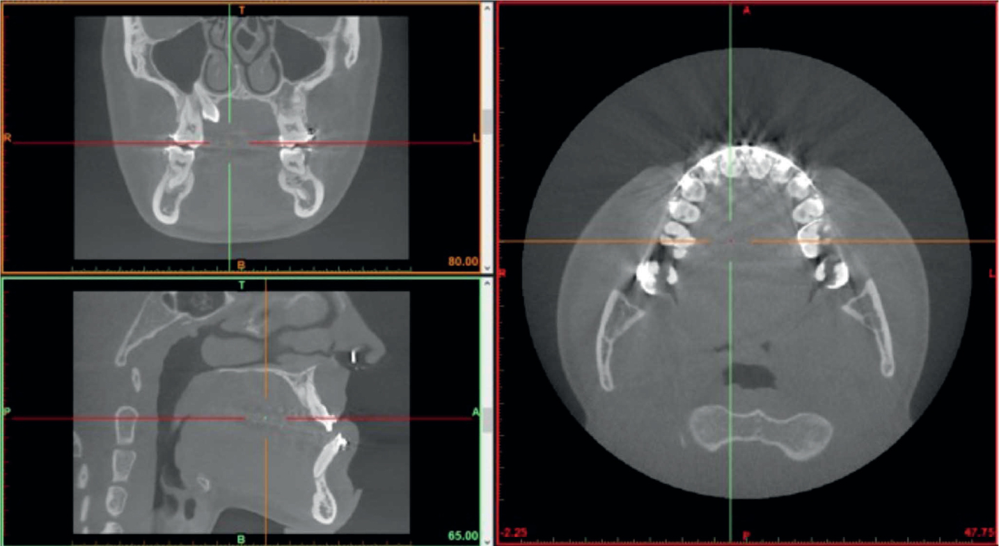
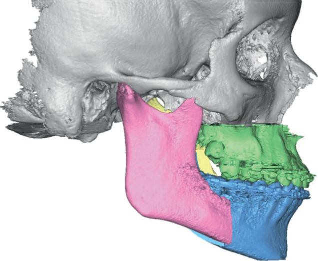
The first stage in orthognathic 3D-VSP is to acquire the relevant clinical imaging of the facial bones, dentition and occlusion. Images of the facial bones are most commonly captured once pre-surgical orthodontic treatment has been completed by taking a computed tomography (CT) or a cone beam CT (CBCT) scan (Figure 1). Initially, 2D data acquisition takes place, the data is then saved in the Digital Imaging and Communications in Medicine (DICOM) format before then being imported into the 3D-VSP software. The software uses a combination of volume and surface rendering techniques to produce a 3D image of the facial structures. The hard tissues are identified manually by setting a grey level threshold, which best separates the hard from the soft tissues. The reconstructed 3D model of the hard tissues can now be segmented into anatomical regions of interest (ROI) (Figure 2). The first stage of segmentation is to detect and delineate the relevant anatomic structures, such as the maxilla and the mandible. Each ROI is then colour coded accordingly to make it easier for the operator to identify them during subsequent digital planning.
Figure 1. A pre-operative orthognathic CBCT scan.Figure 2. 3D reconstructed regions of interest.
The segmentation process should be conducted by a trained engineer or technologist. The process can be carried out manually or by using semi-automated or automated algorithms that form part of the overarching 3D-VSP software package.7 The automated methods of segmentation can be a useful time saving tool. However, the user must rely entirely on the software to accurately detect the relevant structures. This may be problematic when segmenting complex cases (i.e. those with facial asymmetry) or datasets that have a high level of scatter artefacts. Therefore, the use of automated algorithms should be assessed on a case by case basis. The more complex datasets benefit from a joint manual/semi-automated approach.
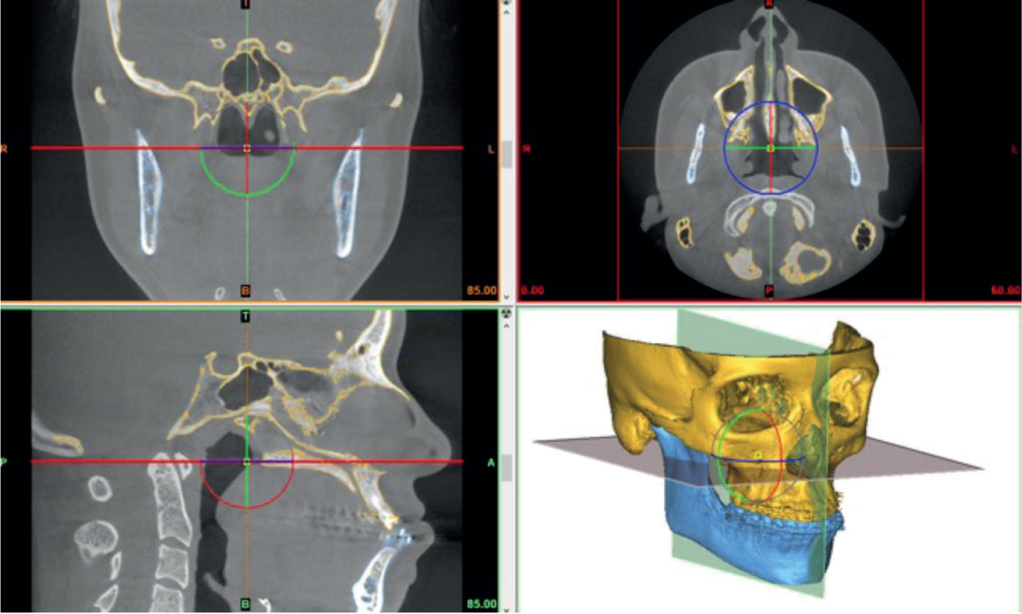
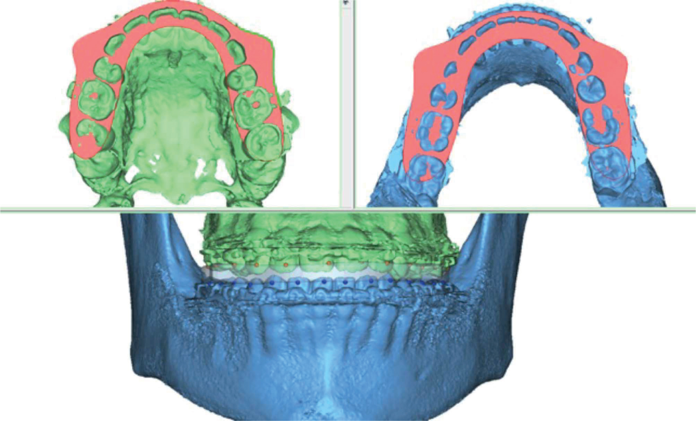
CBCT scans suffer from limited spatial resolution8 which can result in poor image reproduction of the teeth, as shown in Figure 3. Therefore imaging of the maxillary and mandibular dentition and the bite registration, need to be captured in separate high resolution intra-oral scans. These records are usually captured via direct intra-oral scanning, but can also be captured by traditional impression, casting in dental stone and scanning the gypsum model using a benchtop scanner. Once the CBCT has been reconstructed and the subsequent intra-oral scans have been obtained, the images must be merged to create a final virtual patient model. The images are manually aligned using a semi-automated rigid point registration tool (Figure 4). This model is used for the 3D-VSP workflow.
Figure 3. Limited spatial resolution results in low occlusal detail captured by CBCT scanning.Figure 4. The intra-oral scan is aligned with and fused to the CBCT scan using a semi-automated rigid point registration algorithm.
Pre-operative analysis
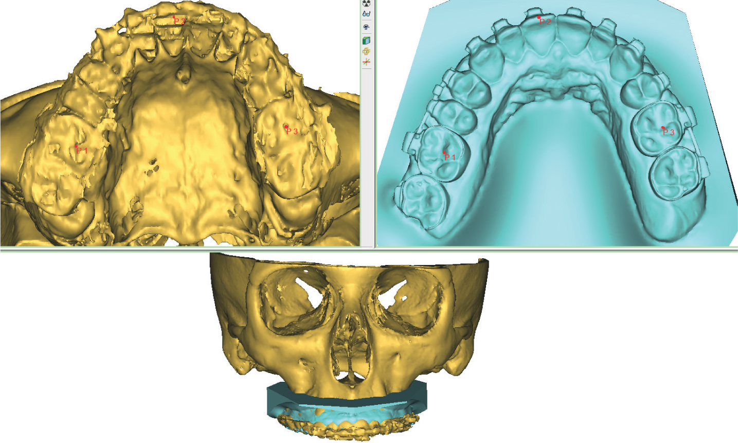
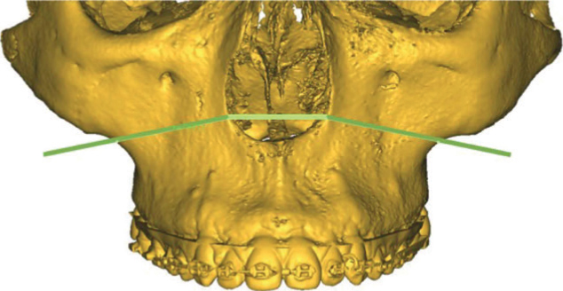
Before simulating orthognathic surgery, the virtual patient model must undergo pre-operative analysis. First, a cephalometric reference plane must be determined; our cases are set according to the Frankfort horizontal plane. The Frankfort plane is commonly used in anteroposterior assessment and to help identify and calculate maxillary canting9 and is set by manually plotting points on four anatomical landmarks (left and right Orbitale and Porion respectively) on the virtual model (Figure 5). Occlusal reference points are also plotted manually using rigid point registration. Points are typically placed on the upper and lower dental midline, incisal tip of the canines and central pit of the first molar. The points are used to track the distance/degrees of intra-operative maxillary and mandibular movement. The next step is to perform the virtual osteotomies according to the surgical plan.
Figure 5. Indicating the Frankfort horizontal reference plane on the 3D model.
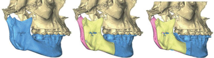
Planning the virtual osteotomy
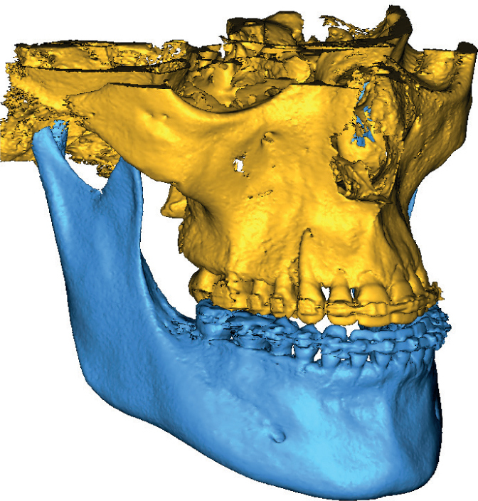
Virtual osteotomies are performed by plotting points of intersection on the virtual patient model (Figure 6). A cutting plane is simulated and adjusted to coincide with the clinical prescription. Adjustments involve ensuring that the chosen saw blade thickness is correct and that the cutting plane does not intersect vital anatomical structures, such as the inferior dental canal and nerve. Le Fort, bilateral sagittal split osteotomy (BSSO), genioplasty and custom osteotomies can all be replicated in the 3D software.
Figure 6. Plotting intersection points for a Le Fort 1 maxillary osteotomy.
Once virtually cut, the osteotomised segments are repositioned by making translational and rotational movements in relation to the sagittal, coronal and transverse planes. The previously plotted occlusal reference points are now used to track the distance/degrees of movement for each segment whilst ensuring the movements adhere to the prescription.
When carrying out 3D-VSP for bimaxillary orthognathic surgery, the virtual maxillary osteotomy is usually the first osteotomy to be undertaken. Typically, the ‘maxilla-first’ sequence is the preferred surgical approach when repositioning the bimaxillary complex. Liebregts et al. (2017) reported that maxilla-first sequencing is more accurate and predictable as higher levels of inaccuracies can arise when manipulating the proximal segments during fixation in the mandible-first approach as this procedure is more prone to potential condylar displacement. 10
Once the maxillary segment has been manipulated into the intermediate position, the remaining mandibular segment is positioned into the final post-operative occlusion. Generally, there are two methods that can be used to achieve the final position.
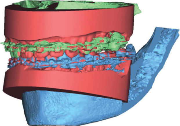
The first method is when the technologist manually replicates the final post-operative occlusion with the surgeon and orthodontist, using handheld dental models. Both, gypsum models taken from traditional alginate impressions or 3D printed pre-surgical intra-oral scans will be sufficient. The predetermined final position is identified on the models and the occlusion is scanned using a benchtop scanner and imported into the 3D-VSP software as an ‘occlusal registration guide’. Using the previously mentioned rigid point registration algorithm, the remaining osteotomised segment is aligned according to the imported occlusal registration guide (Figure 7). Reverse engineering the final occlusion is one way of achieving the optimal post-operative position.
Figure 7. The final occlusion alignment using the imported occlusal registration guide and the rigid point registration algorithm.
The second method involves utilising a series of embedded tools in the 3D-VSP software that allow the user to autorotate the mandible, detect bony collisions and to achieve maximum intercuspation. However, from personal experience determining the final position solely using the embedded tools is difficult, as the level of on-screen occlusal contact is not always apparent. This issue could be simplified with the introduction of haptic technology. Haptic technology is currently used in surgical simulation, 3D sculpting, data visualisation and computer gaming. This technology provides tactile feedback which recreates a sense of touch. This is achieved by applying vibrations, force or motion to the user. Therefore, virtual objects in a computerised environment will appear real and tangible.11
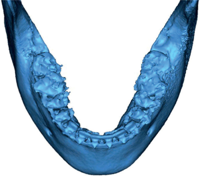
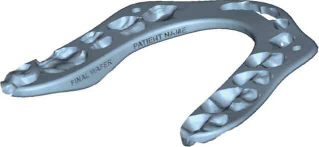
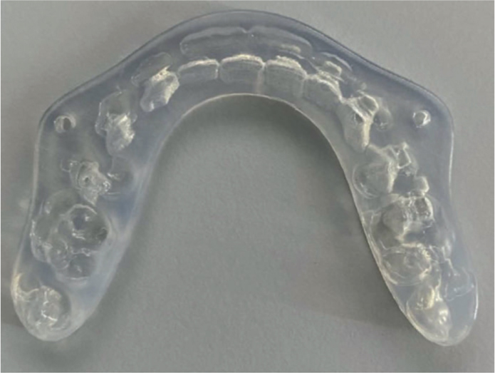
Once the intermediate and final post-operative occlusions have been established (Figure 8), the occlusal wafer design process is undertaken. A wafer is virtually constructed by marking the points of intersection on the incisal and cuspal regions of the upper and lower dentition (Figure 9). The software auto-generates a digital wafer design according to the plotted points. The level of retention, material thickness and global profile of the wafer can be adjusted according to the clinical need. At this stage the wafers can also be labelled so that they can be identified with ease (Figure 10). The completed wafers are saved in the STL file format and exported to the 3D printer for fabrication (Figure 11).
Figure 8. The planned final post-operative position.Figure 9. Virtual construction of an orthognathic wafer. Points of intersection on the incisal and cuspal regions of the upper and lower dentition are marked and a wafer profile is generated.Figure 10. Virtual orthognathic wafer design marked and labelled accordingly.Figure 11. A 3D printed orthognathic wafer with accompanying wire holes for intra-oral fixation.
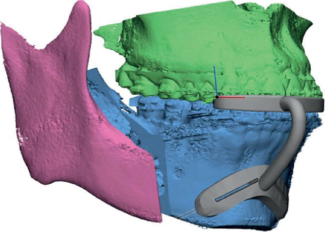
Surgical guide design
The 3D-VSP can be transferred from the workstation and replicated in the operating theatre with the use of patient-specific surgical cutting guides and repositioning jigs (Figure 12). The use of such devices has been shown to improve intra-operative accuracy and post-operative results. 12.
Figure 12. Osseous genioplasty surgical cutting guide design. The guide is designed to be inserted intra-orally and held in place using an occlusal positioning jig and fixation wire.
Case studies
The following two clinical cases have undergone joint orthodontic/orthognathic treatment by means of a 3D-VSP workflow.
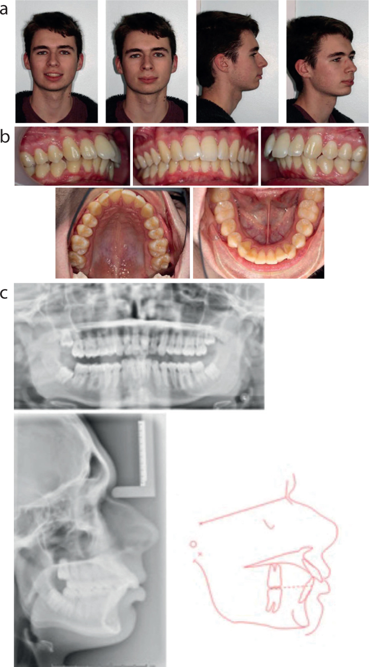
Case 1
Case 1 relates to a 17 year old male whose main concern was his bite. He presented with a Class II division 1 incisor relationship on a Class II skeletal pattern with decreased lower anterior face height and competent lips (Figure 13). His malocclusion was complicated by an increased overjet of 8 mm to the UR1, 6 mm to the UL1 and a proclined lower labial segment. The centrelines were coincident and there was mild crowding of the upper and lower arches. At the initial assessment, the patient was given the options of a) do nothing, b) orthodontic camouflage including maxillary extractions to reduce the overjet or c) a combined orthodontic/orthognathic approach. Having considered the options, the patient returned to the Joint orthodontic-orthognathic MDT clinic and opted for the following treatment plan:
Extraction of LR8, LR5, LL5, LL8, UR5, UL5
Pre-surgical orthodontic treatment utilising upper and lower fixed appliances to level, align, decompensate and coordinate the arches
Mandibular advancement surgery
Post-surgical orthodontics for detailing and finishing of the occlusion
The 3D virtual surgical plan (Figure 14) consisted of:
Bilateral sagittal split osteotomy
Mandibular advancement of 7 mm
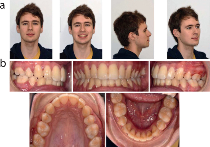
The pre-surgical and end of treatment records are shown in Figures 15 and 16.
Figure 14. Clinical case 1 3-dimensional virtual surgical planning showing 7 mm mandibular advancement and 1.5 mm rotation to the left.Figure 15. Clinical case 1 pre-surgical records (a) extra-oral photos, (b) intra-oral photos, (c) lateral cephalogram and tracing (SNA=90°, SNB=83°, ANB=7°, MxP/MnP=23°, UI/MxP=113°, LI/MnP=99°).Figure 16. Clinical case 1 end of treatment records (a) extra-oral photos, (b) intra-oral photos.
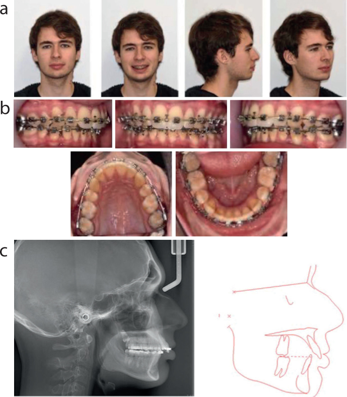
Case 2
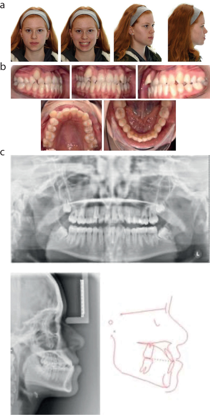
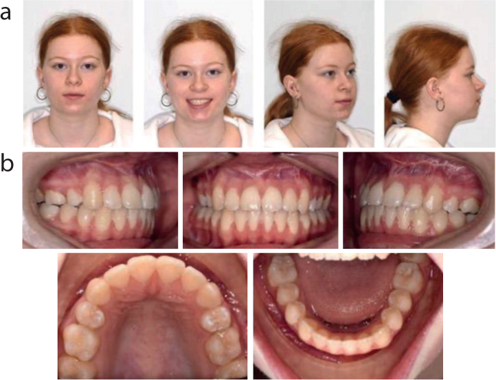
This case relates to a 15 year old female patient who presented with a Class III incisor relationship on a Class III skeletal pattern with average anterior face height and competent lips (Figure 17). Her main concern was that her lower teeth were further forwards than her upper teeth.
Figure 17. Clinical case 2 pre-treatment records (a) extra-oral photos, (b) intra-oral photos, (c) radiographs and cephalometric tracing (SNA=86°, SNB=88°, ANB=-2°, MxP/MnP=19°, UI/MxP=125, LI/MnP=97°)
Her malocclusion was complicated by severe crowding of the upper arch, mild crowding of the lower arch, a reverse overjet of 2 mm and a crossbite associated with UR652, UL23456 with anterior displacement. There was a centreline discrepancy with the upper shifted 1 mm to the right. Following attendance at the Joint orthodontic-orthognathic MDT clinic, the patient and her family agreed to the following treatment plan:
Extraction of UR4, UL4, LR8, LL8
Pre-surgical orthodontics including upper and lower fixed appliances to align, level, decompensate and coordinate the arches
Bimaxillary orthognathic surgery
Post-surgical orthodontics for detailing of the occlusion
Upper and lower vacuum-formed retainers
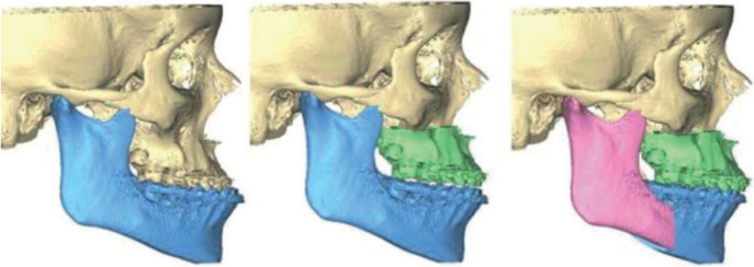
The 3D virtual surgical plan (Figure 18) consisted of:
Le Fort 1 maxillary osteotomy
Maxillary advancement of 3 mm
Bilateral sagittal split osteotomy
Mandibular setback of 4 mm
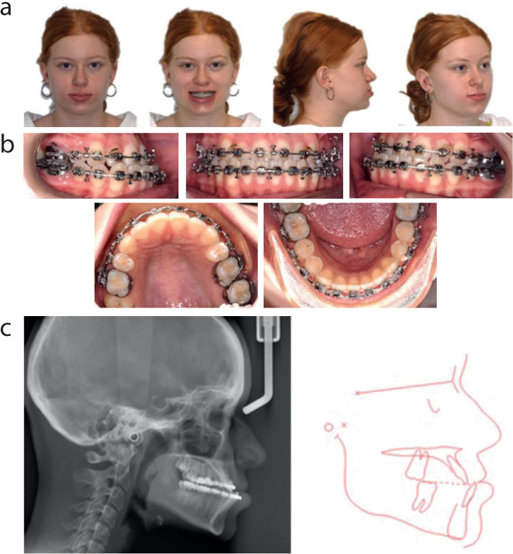
The pre-surgical and end of treatment records are shown in Figures 19 and 20 respectively.
Figure 18. Clinical case 2 3-dimensional virtual surgical planning for bimaxillary osteotomy including 3 mm maxillary advancement, 4.3 mm mandibular setback to fit.Figure 19. Clinical case 2 pre-surgical records (a) extra-oral photos, (b) intra-oral photos, (c) lateral cephalogram and tracing (SNA=85°, SNB=90°, ANB=-5°, MxP/MnP=22°, UI/MxP=121°, LI/MnP=99°).Figure 20. Clinical case 2 end of treatment (a) extra-oral photos, (b) intra-oral photos.
Conclusions
The use of digital workflows in joint orthodontic/orthognathic planning has become increasingly popular. 3D-VSP has the potential to improve clinical and laboratory efficiency whilst enhancing surgical precision, consistency and reproducibility of treatment. However, a 3D-VSP service requires substantial investment as well as the development and recruitment of technologists with a specialist skill set. The two clinical cases presented illustrate how 3D-VSP and surgical simulation is used to manage such cases.